Please go to “video presentations” section to watch all aspects in details, here is simple description of the PCL lock mechanism and why it is so secure.
Below few colour coded pictures of the PCL mechanism working in safe door or any residential door. Please remember that the design and the shape below is as simple as possible because I am not CAD specialist. The purpose is not to focus on design as the shape but rather on working principia and why it is so unique ans extremely secure.
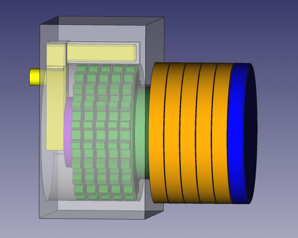
- PCL is build from few components:
- Combinations Wheels (Dark Green) – it is flexible how many combination wheels is inside and how many numbers on each wheel (number of teeth).
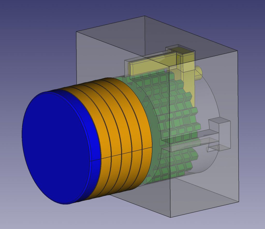
- Combination knobs (Orange) – each knob is directly connected with one combination wheel. The shape of them could be different. There will be numbers on each orange knob corresponding with the space between teeth on the green wheels. In our example is 5 orange knobs with 20 numbers each. (No numbers visible on pictures).
- Open/Close knob (Dark Blue) – this is with long shaft through entire PCL directly connected with Actuator (yellow). You will see it in video presentations.
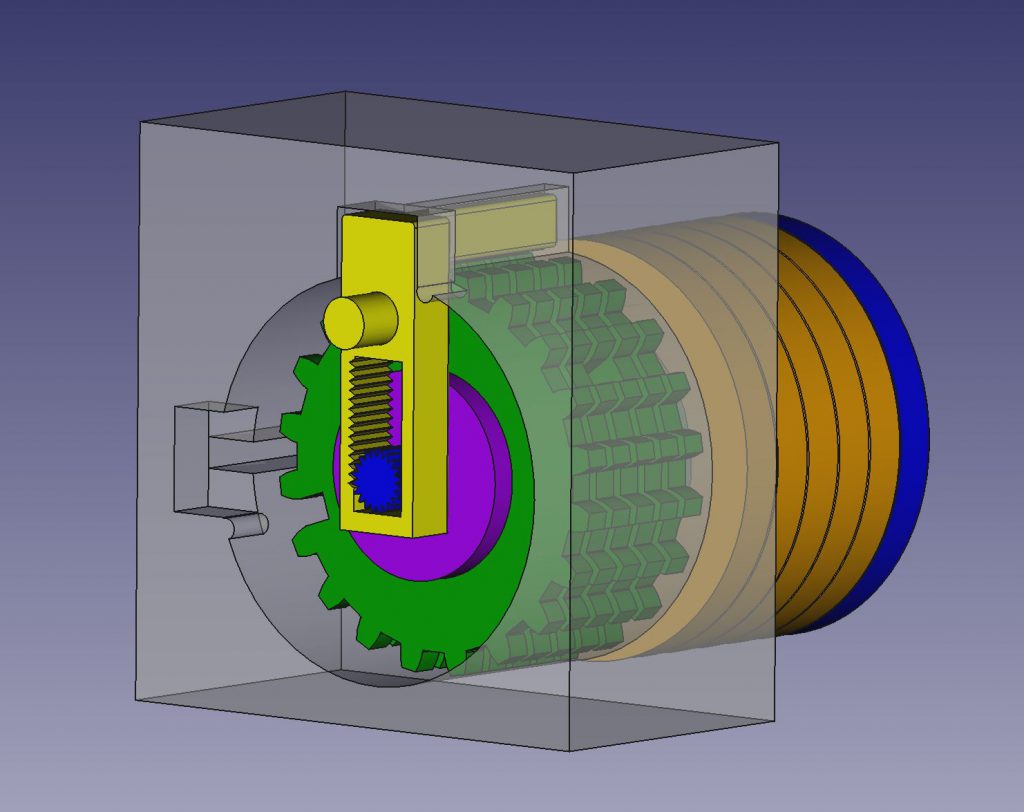
- Actuator – (Yellow) – this is unique part working as open/close “bridge” protecting the PCL to be open if wrong code is set up and allow to open when correct combination is set.
- Security Ring – (Magenta) – it is nut screwed on the shaft and holds all mechanism in place.
- PCL housing – (Transparent) – it is part od the safe door or residential door.
- PCL in close state as is shown above allow the user to freely rotate every orange combination wheel 360 degree in both direction and set up correct combination against the mark on the housing. There is air gap between yellow and green parts in this close state, no touch.
- Setting correct combination is based on alignment of all deeper cuts on green wheels under the yellow Actuator and from outside just to set all correct numbers in one row against the mark on the housing.
- Opening the PCL: IMPORTANT -There is air gap, no physical touch between yellow Actuator and green Combination Wheels.
- When you set up correct code all deep cuts on green wheels are under the yellow Actuator.
- Then user can lower the Actuator by rotating the blue Open/Close knob. This low position of the yellow Actuator enable to rotate entire PCL mechanism i.e. 90 degree left or right and to Open the PCL.
- Then the user has the possibility to leave PCL mechanism in secure Open or secure Close position. This unique feature is important for residential doors.
- False combination attack attempt:
- When the false code is set up not all deep cuts on green wheels will be in place below the yellow Actuator and one or more false gates are under the yellow Actuator. In this state the yellow Actuator can be lower only partially not enough to enable the rotation to Open. In this state all Orange knobs are tied up (bondage by Actuator upper bar) together by yellow Actuator and is not possible to rotate or change the combination anymore. This unique feature force the attacker to guess the combination one-by-one and makes this PCL mechanism practically uncrackable.
To find all details please go to “Video Presentations” section or other pages, please watch all videos in the logic sequence Part 1 to 6 or jump directly to Summary video if you have no time.